Output Jobs
At the end of every PCB project, we need to generate various production data files, e.g. for PCB manufacturing, PCB assembly, or simply for documentation purposes. LibrePCB provides a unified interface to generate any kind of production data for a project. It is called Output Jobs.
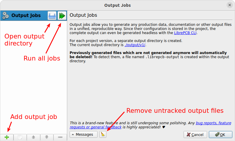
From either the schematic- or board editor, open the Output Jobs dialog with the menu item or by pressing F11:
Output Directory
Any output files are always generated into the project directory
output/<VERSION>/ where <VERSION> represents the project’s version
number as specified in the project setup dialog (F6). So for the
default version number v1, the output data goes to output/v1/ within
the project directory.
|
Since existing output files are overwritten without prompt when running jobs, always make sure the version number has the desired value (e.g. bump it after releasing a PCB version). |
Note that LibrePCB automatically creates a file named .librepcb-output
within this output directory. It is used internally to detect untracked
output files (see details below).
Add Jobs
The list of output jobs is initially empty for every new project. So for any output data you like to generate, you need to add a corresponding job with the plus button at the bottom left. This will add a new job to the list on the left side of the dialog. Select the new job to modify its properties.
This way you can add as many jobs as you need, even multiple jobs of the same type are allowed (e.g. if different settings are needed). The available job types and their configuration options are listed below.
Run Jobs
Once you added all desired jobs, you can run them either individually or all at once with the corresponding buttons in the job list. Note that every run overwrites the output files of previous runs. In addition, a run also removes previously generated files of the same job, for example after modifying the output file path configuration. This ensures that no outdated files are left over in the output directory.
Untracked Output Files
After running any output job, LibrePCB automatically scans the output directory for any untracked files, i.e. files not generated by any output job. For example when deleting an output job, its previously generated output files are still left over in the output directory. As this might not be intended, LibrePCB reports them in the output messages and provides a button to delete them. It is your choice to either keep or delete these files.
Common Configuration Options
Although the configuration options differ from job to job, there are some options available in several jobs so these are documented here:
- Name
-
Just a user-defined, unique name to identify each job in the list of all jobs.
- Output
-
File path of the file(s) to generate, relative to the Output Directory. May use placeholders like
{{PROJECT}}or{{VERSION}}. For example the output path{{PROJECT}}_{{VERSION}}_BOM.csvmight result in the full output file pathoutput/v1/MyProject_v1_BOM.csvrelative to the project’s root directory. - Boards
-
Selection of boards to run the job for. For example if a project contains multiple boards and you want to generate Gerber files for each of them, this option allows to do that with a single output job instead of creating separate output jobs for each board. The available values are:
-
Default: Run the job only for the default board (which is always the first board in a project). So the job is run exactly once, except if the project contains no board at all; then the job is not run.
-
All: Run the job for each existing board. If no board exists, the job is not run.
-
Custom: Manually select the boards the job shall run for (0..n). Some jobs also provide the special value "None" which means a job is run outside the context of a board.
If multiple boards are selected, you have to add the placeholder
{{BOARD}}(or any other board-specific attribute) to the output file path to avoid generating conflicting files!
-
- Assembly Variants
-
Similar to the Boards option, this option allows to specify the assembly variants a job shall run for. For example if a project contains multiple assembly variants and you want to generate a separate BOM for each of them, this option allows to do that with a single output job instead of creating separate output jobs for each assembly variant. The available values are:
-
Default: Run the job only for the default assembly variant (which is always the first one). So the job is run exactly once.
-
All: Run the job for each existing assembly variant.
-
Custom: Manually select the assembly variants the job shall run for (0..n).
If multiple assembly variants are selected, you have to add the placeholder
{{VARIANT}}to the output file path to avoid generating conflicting files!
-
To help understanding the Boards and Assembly Variants options, consider a project with the boards "Board1" and "Board2", and the assembly variants "AV1" and "AV2". If you set both configuration options to "All", a job is run for each combination of them, i.e. four times:
-
Run 1:
{{BOARD}}=Board1,{{VARIANT}}=AV1 -
Run 2:
{{BOARD}}=Board1,{{VARIANT}}=AV2 -
Run 3:
{{BOARD}}=Board2,{{VARIANT}}=AV1 -
Run 4:
{{BOARD}}=Board2,{{VARIANT}}=AV2
Job Types
This section descibes all the available job types and their configuration options.
PDF/Image
Generates a PDF or image(s) containing either the schematics, the board(s) or both. For convenience, there are two built-in presets to quickly generate frequently needed documents:
-
Schematic PDF/Image: Adds a job to generate a PDF with the schematics.
-
Board Assembly PDF/Image: Adds a job to generate a PDF with top/bottom assembly plans for the board(s).
Both presets add the same type of output job, just with different initial configuration options.
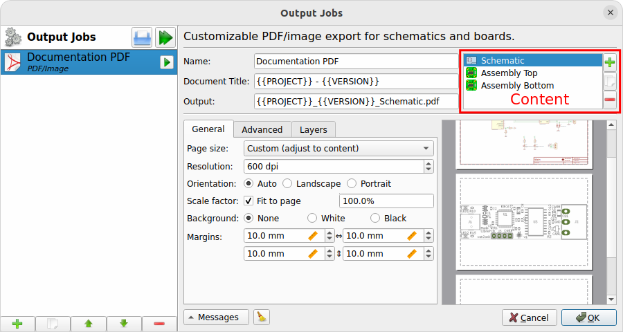
- Name
- Document Title
-
Title of the generated document, to be set in the metadata of the output file. This option only has an effect if the output file type is either PDF or SVG. Placeholders like
{{PROJECT}}may be used in the value. - Output
-
See Common Configuration Options. The specified file extension determines what output file format is used. The extension
.pdfgenerates a single PDF containing all pages. The extension.svggenerates a separate SVG for each page. Pixmap extensions like.pnggenerate a separate image file for each page. Note that the supported pixmap extensions depend on the platform, but.pngshould always be available.If multiple image files are generated, a page number is automatically appended to the file name, for example the output path
image.pngmay generate the filesimage1.pngandimage2.png. - Content (list view on the right side)
-
The actual content of the output document is specified in the list view on the right side. A content item could either be the schematic or the board, while for the board there exist two different presets Board Image and Assembly Top/Bottom for convenience. The schematic type adds 0..n pages to the output (depending on how many sheets your project has), while a board type adds one page per board to the output document. So with this output job you can freely choose whether the output document represents a schematic, or a board, or even contains both. The pages in the output document are added in the same order as the specified content items.
- General/Advanced
-
These options affect the layout of the output document and should be mostly self-explaining. Note that these options refer to the currently selected content item (the list at the top right), so they are independent for each content item.
- Layers
-
Selection of layers to be included in the output document, and their color. The color of each layer can be changed by double-clicking on a layer list item. The colors are not takes from your workspace settings to make this output job independent of user settings. Note that these layer settings refer to the currently selected content item (the list at the top right), so they are independent for each content item.
Gerber/Excellon
Generates RS-274X (Gerber X2) and IPC-NC-349/XNC (Excellon) files for PCB production. For convenience, there are two built-in presets available:
-
Gerber/Excellon: Uses default options with
.gbrfile extension according recommendation by the Gerber standard. -
Gerber/Excellon (Protel style): Configures Protel file extensions and sets some options for compatibility with cheap PCB manufacturers.
Both presets add the same type of output job, just with different initial configuration options. Please check the documentation of your desired PCB manufacturer which options are supported. If you intend to order the PCB through LibrePCB Fab, you don’t need to add a Gerber/Excellon output job at all.
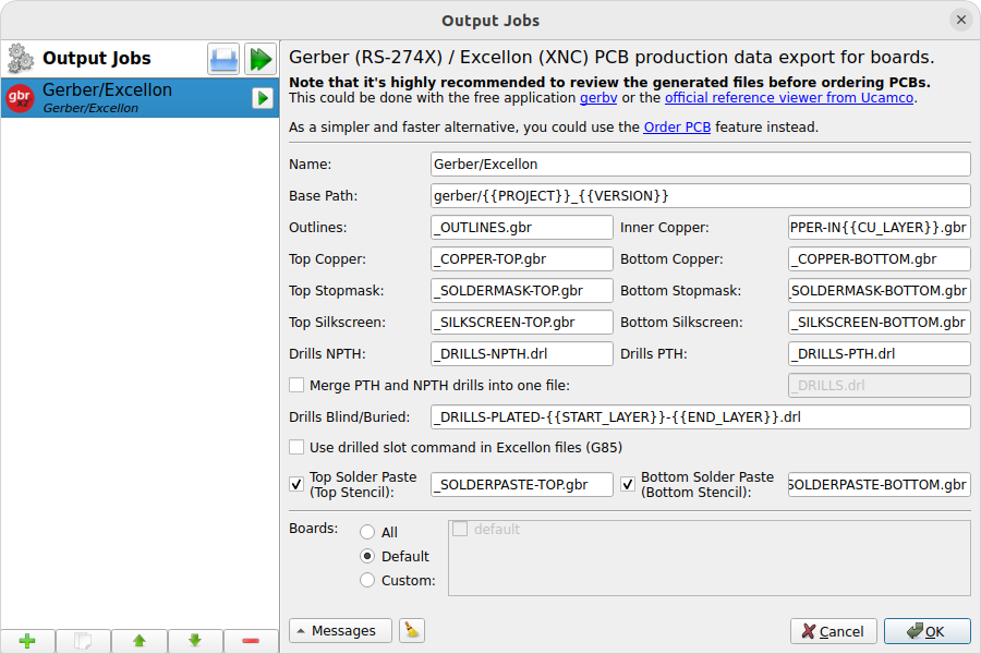
- Name
- Base Path
-
Specifies the common output path prefix to be used for all the output files. So the actual output file paths consist of this path appended by the corresponding output file suffix as explained below. See also the Output option documented in Common Configuration Options.
- Outlines
-
Output file suffix for the board outlines. Will contain all objects on the Board Outlines and Board Cutouts layers.
- Top/Bottom Copper
-
Output file suffix for the Top Copper resp. Bottom Copper layers.
- Inner Copper
-
Output file suffix for the Inner Copper layers. For each used inner layer, a separate Gerber file is created. Therefore the placeholder
{{CU_Layer}}needs to be used, which is substituted by the inner layer number ("1" for the first inner layer, just below Top Copper). - Top/Bottom Stopmask
-
Output file suffix for the Top Stop Mask resp. Bottom Stop Mask layers.
- Top/Bottom Silkscreen
-
Output file suffix for the top resp. bottom silkscreen layers as configured in the board setup dialog. Note that these files are only generated when enabled in the board setup dialog.
- Drills NPTH
-
Output file suffix for the non-plated through-hole Excellon drill file, i.e. all drills which are called Hole in LibrePCB (including slotted holes).
- Drills PTH
-
Output file suffix for the plated through-hole Excellon drill file, i.e. all through-hole pads and through-hole vias (including slotted pads).
- Merge PTH and NPTH drills into one file
-
If this option is enabled, all through-hole drills are exported into a single Excellon drill file (with the suffix provided next to this option) instead of generating separate files. So the Drills NPTH and Drills PTH files won’t be created if this option is checked. Note that generally this option is not recommended, but some PCB manufacturers (especially cheap ones) are not able to handle separate files for PTH and NPTH. In that case, this option needs to be enabled.
- Drills Blind/Buried
-
If blind/buried vias are used in the board, a separate Excellon drill file will be created for each different drill layer pair. This option specifies the file name suffix for these files. Since multiple files might be created, the placeholders
{{START_LAYER}}and{{END_LAYER}}need to be used, which will be substituted by either "TOP", "BOTTOM" or "INx" where "x" is the inner layer number starting at 1. Or alternatively, the placeholders{{START_NUMBER}}and{{END_NUMBER}}are also available which are substituted by just a number (1 = top layer, 2 = first inner layer etc.). - Use drilled slot command in Excellon files (G85)
-
If your board contains slots (plated or non-plated), they are exported to Gerber files with G00..G03 commands by default. By checking this option, the G85 slot command will be used instead. This is generally not recommended, but some PCB manufacturers may not support the G00..G03 commands. In that case, the G85 command might need to be used instead.
- Top/Bottom Solder Paste
-
Output file suffix for the Top Solder Paste resp. Bottom Solder Paste layers. These files are not directly used for the PCB production, but for the SMD stencil to apply solder paste on the PCB. If you don’t need a stencil, the generation of these files should be disabled by unchecking the corresponding checkboxes.
- Boards
Pick&Place CSV
Generates a pick&place position file containing the coordinates of each device on the PCB as comma-separated values (CSV). This file is needed for automatic PCB assembly by pick&place machines. Alternatively, the Gerber X3 format might be used instead, which is provided by the output job type Pick&Place Gerber X3.
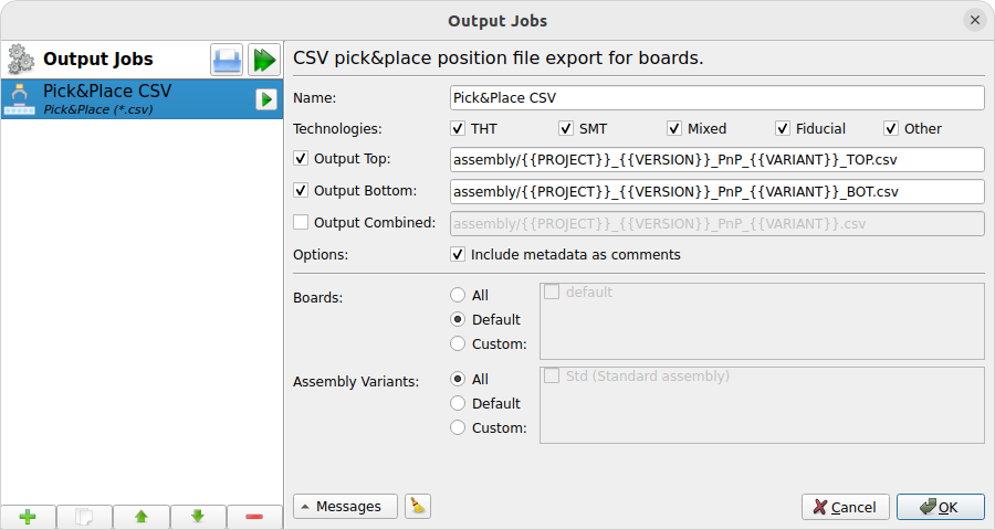
- Name
- Technologies
-
Selection of device types to be included in the output file. For example if only "THT" is selected, you’ll get a CSV file containing only THT devices. The available technologies are:
-
THT: Pure through-hole devices, i.e. all leads are THT.
-
SMT: Pure surface-mount devices, i.e. all leads are SMT.
-
Mixed: Devices containing both through-hole and surface-mount loads (for example SMT connectors wich THT pads for mechanical stability).
-
Fiducial: Whether fiducial coordinates (for PCB alignment) should be contained in the pick&place file or not.
-
Other: Any other special device types, for example pure mechanical devices to be mounted with screws instead of soldering.
-
- Output Top/Bottom/Combined
-
See Common Configuration Options. Three different output paths can be configured to get either separate files for top/bottom devices, or a single file for all devices. Must have file extension
.csv.Use the checkboxes to select the files to generate.
- Include metadata as comments
-
If checked, the output CSV files will contain a header comment with some metadata like project name, generation date etc. This is helpful for traceability/documentation purposes, but some CSV readers fail to ignore this comment. If you’re unsure, just uncheck this option as this is always safe.
- Boards
- Assembly Variants
Pick&Place Gerber X3
Same as Pick&Place CSV, but generating Gerber X3 pick&place files instead of CSV files. The advantage of this format is that it’s standardized, while there’s no standard for CSV pick&place files so CSV might cause issues or at least involves manual effort during pick&place machine setup. However, Gerber X3 is not as widely supported by assembly houses as CSV files.
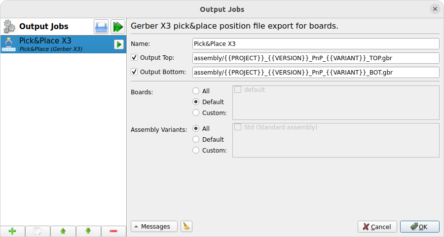
- Name
- Output Top/Bottom
-
See Common Configuration Options. Two different output paths can be configured to get separate files for top/bottom devices. Should have file extension
.gbr.Use the checkboxes to select the files to generate.
- Boards
- Assembly Variants
Netlist
Generates an IPC D-356A netlist used for automatic electrical testing of the PCB.
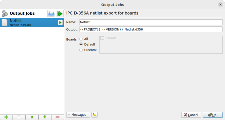
- Name
- Output
-
See Common Configuration Options. Must have file extension
.d356. - Boards
Bill Of Materials
Generates a bill of materials (BOM) in CSV format, containing all devices to be ordered for a particular assembly variant.
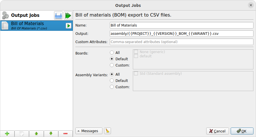
- Name
- Output
-
See Common Configuration Options. Must have file extension
.csv. - Custom Attributes
-
This option allows to add custom additional columns to the output CSV file. For this purpose, attributes are used. For example the value "DIGIKEY,MOUSER" adds the two columns "DIGIKEY" and "MOUSER" to the CSV, with the corresponding values of these attributes on devices. The value will be empty for devices not providing a particular attribute.
When adding the suffix
[]to a custom attribute, it is considered as a per-part attribute instead of a global attribute. This means the attribute is not exported to the BOM only once, but once per part of a component. This might be desired if some components have alternative (i.e. multiple) part numbers specified. See Assembly Data for details. - Boards
- Assembly Variants
|
The actual number of columns in the output file depends on whether (and how many) alternative part numbers are specified on components. The component with the most part numbers defines how many columns the BOM CSV will have. See Assembly Data for details. The order and name of columns is as follows:
For the typical use-case (without custom attributes and no alternative part numbers specified in schematics), the CSV header looks as following: Quantity,Designators,Package,Value,MPN,Manufacturer If at least one component has specified one alternative part number, three additional columns will appear: Quantity,Designators,Package,Value,MPN,Manufacturer,Value[2],MPN[2],Manufacturer[2] |
3D Model
Exports a board as a 3D STEP file for importing it in a mechanical CAD (MCAD). Note that in contrast to the built-in 3D viewer, the exported STEP model won’t contain details like copper traces, solder resist or silkscreen.
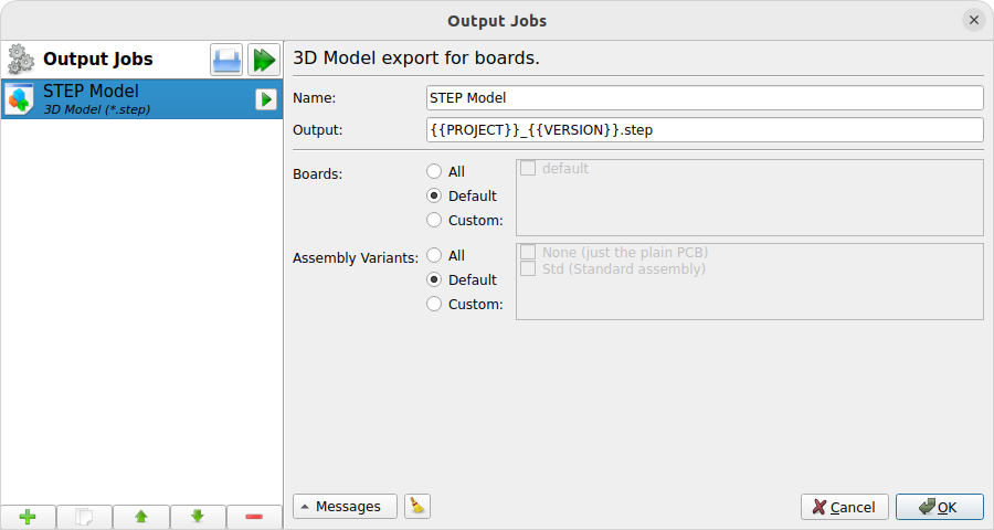
- Name
- Output
-
See Common Configuration Options. Must have file extension
.stepor.stp. - Boards
- Assembly Variants
-
See Common Configuration Options. Only devices contained in the corresponding assembly variant will be exported. The special value "None" means that only the plain PCB is exported, without any devices on it.
File Copy
Special job which actually doesn’t generate anything, but copies an existing file into the output directory. This is intended for example to include custom files like instruction notes in the data to be sent to the PCB manufacturer or assembly house.
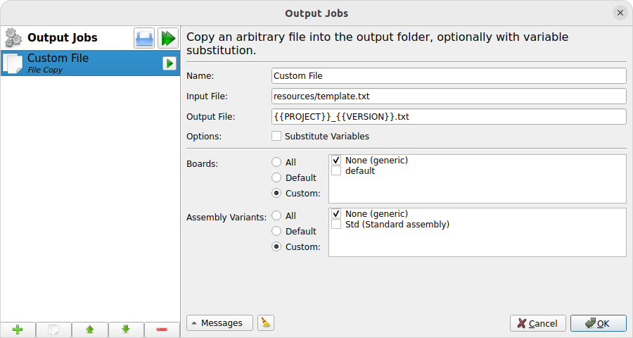
- Name
- Input File
-
Path to the (existing) input file to copy, relative to the project’s root directory. It’s highly recommended to place this file within the
resources/directory (at least do not place it in theoutput/directory!). - Output File
-
See Output in Common Configuration Options. Should have the same file extension as the input file.
- Substitute Variables
-
If checked, the input file is read by LibrePCB and any occurrences of attribute placeholders like
{{PROJECT}},{{VERSION}}or{{DATE}}will be substituted by their value before writing that content to the output destination. Project attributes are always available, while board attributes and assembly variant attributes are only available if the job is run in the context of a board resp. assembly variant (see options below).That this option shall only be used on text files, not on binary input files.
- Boards
-
See Common Configuration Options. The special value "None" means that this job does not run in the context of a board and will be run exactly once, no matter how many boards the project contains.
- Assembly Variants
-
See Common Configuration Options. The special value "None" means that this job does not run in the context of an assembly variant and will be run exactly once, no matter how many assembly variants the project contains.
Archive
Special output job which combines the output of other jobs in a single archive file (e.g. ZIP).
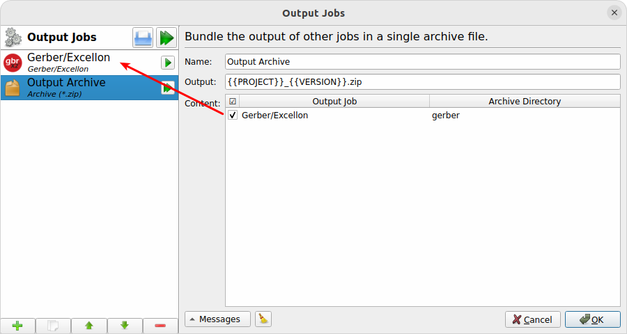
- Name
- Output
-
See Common Configuration Options. The file extension specifies the type of archive to create. Currently only
.zipis supported. - Content
-
Selection of jobs which output files shall be added to the archive. Note that only jobs listed prior to the archive job may be selected to ensure no cyclic dependencies can be created (an error will be raised when violating this rule).
All output files of the selected jobs are added to the root directory of the archive, with their original file name but with any subdirectory stripped. It’s not possible to specify different file names just for the archive. However, the Archive Directory column allows to move all files of a particular job into a custom subdirectory (for example to move all Gerber files into a
gerber/directory and all pick&place files intoassembly/).
|
When running an archive job, LibrePCB will automatically run all its dependent jobs first to generate their output. |
Project Data
Generates a custom JSON file containing some metadata about the project. This is not intended for end users but it’s still listed publicly for completeness.
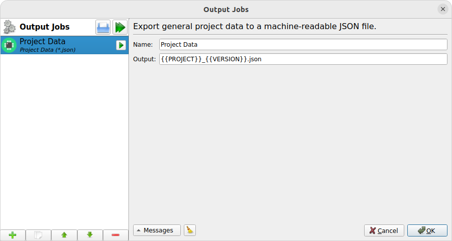
- Name
- Output
-
See Common Configuration Options. Should have file extension
.json.
Project Archive
Exports the whole project to a single *.lppz file (which is simply a ZIP).
Intended to keep a snapshot of a particular project version which can
directly be opened with LibrePCB from the desktop file manager. In
addition, this file could be uploaded to
fab.librepcb.org to (re-)order the PCB.
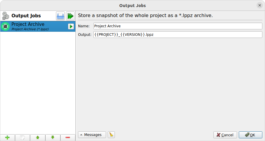
- Name
- Output
-
See Common Configuration Options. Must have file extension
.lppz.