Assembly Data
This chapter explains how to specify assembly data like MPNs[1] in your project to get an accurate BOM[2] ready to order the correct parts. LibrePCB supports many different use-cases which will be explained below.
|
Assembly data is a rather advanced topic, and often not that relevant for simple hobby projects which are assembled by hand. So for your first steps with LibrePCB, you could simply ignore this whole topic. LibrePCB will let you generate a BOM for your project anyway, it might just be less accurate (e.g. missing exact MPNs). |
Assembly Variants
First of all, you should understand the concept of assembly variants because the assembly data of each part is related to an assembly variant.
Basically an assembly variant simply represents a variation of the BOM. For each assembly variant you’ll get a separate BOM which may differ in which parts are contained, or what MPNs are specified for the parts. So if you project contains 5 assembly variants, the BOM export will create 5 BOM files.
Every project requires to contain at least one assembly variant. LibrePCB therefore automatically adds a default variant called Std when you create a new project. In many cases, this is sufficient and you don’t need to care about assembly variants at all.
However, there are use-cases where you want to generate different BOMs for a single PCB project. Usually this is desired if multiple different products are created from the same PCB, differing only on the assembled parts. For example the same PCB could be assembled with either an RS485 interface, or with an Ethernet interface (or both). Or a voltage regulator module can either output 3.3V or 5V, depending on the value of an assembled resistor.
To define the assembly variants, open or press F6 and navigate to the Assembly Variants tab:
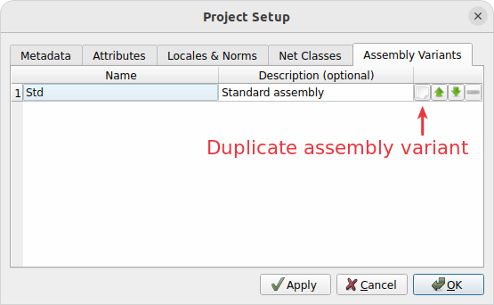
A new assembly variant can only be added by duplicating an existing one. The new variant will then initially contain exactly the same parts as the existing one.
|
It’s highly recommended to keep the variant name as short as possible (e.g. just 5V instead of OutputVoltage5V) because it will be part of the file name of the exported BOMs. It must therefore also not contain any special characters. A more descriptive name may by specified in the Description field. |
If one of the variants is considered as the default or most used variant, it’s recommended to move it to the top of the list. Some features in LibrePCB will respect only the first assembly variant, no matter how many are defined.
Component Assembly Data
The assembly variants explained above are defined at project scope, i.e. they are valid for a whole project. This section now describes what assembly data is defined on component scope.
Add Component By MPN
Often, assembly data for a component consists of a manufacturer name and an MPN (the part number). Those two values are sufficient to know which part needs to be ordered from your supplier.
The easiest way to add this data to a component is at the time when you add a new component to the schematic. Maybe you remember this screenshot from the Quickstart Tutorial:
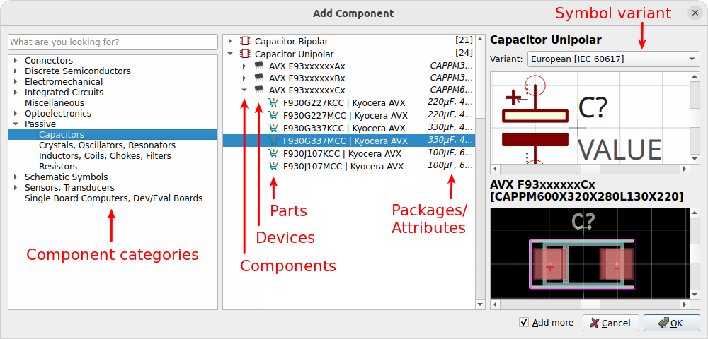
You can add either a component, a device or a part to the schematic. Components and devices however do not contain any assembly data. But if you add a part, the component in the schematic will automatically contain the MPN and (usually) the manufacturer as assembly data. So in that case, no manual action is needed anymore.
Assembly Data Editor
No matter if you added components by MPN to the schematic or not, the assembly data of a component can always be manually edited in its properties dialog. This is also required for more complex scenarios, e.g. if you like to exclude a component from a particular assembly variant or if you like to specify second source parts.
Click on Properties from the components context menu or select the component in the schematic and press E:
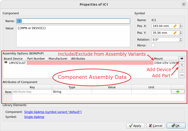
Each row in this table represents one assembly data set (or a part). Note that each part is valid only for a particular device — for example an OpAmp might be provided in a SOT23-5 package by one device, and in a DIP8 package by another device. So it’s clear their order information will be different. Thus the first column specifies for which device a part is valid for.
In the last column, you can specify for which assembly variants a part is valid for, i.e. in which variants the part shall be assembled.
The three columns in the middle contain the actual assembly data which
is accessed by the BOM export. This might be an MPN and manufacturer name,
but it might also be just a single attribute like CAPACITANCE=100nF.
Empty fields do not mean the part will be excluded from the BOM — the
corresponding BOM fields will just be empty as well.
|
Unfortunately the UI is be a bit confusing at the moment, we’ll try to improve it in upcoming releases. The most important thing to know is that the attributes editor at the bottom is related to the selected row in the assembly options table. So to specify an attribute for a particular assembly option, select the corresponding row and add the attribute to the table afterwards. If no assembly option is selected, the attributes table displays the attributes set directly on the component (i.e. attributes not depending on assembly variants). |
No worries if you don’t fully understand the concept yet. The sections below will show you concrete examples for each of the possible use-cases.
Example: Specify MPN
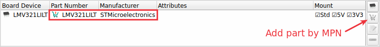
As mentioned above, each part could either be represented by an MPN plus manufacturer name, or just as simple attributes. If you want to have an MPN contained in the BOM, click on the Add Part By MPN button and choose a part. If the desired part doesn’t exist in the library, just choose a device instead and type in the MPN and manufacturer manually. The result should then look like this:
|
Example: Specify Attributes
If you don’t care about an exact MPN but just want to specify some attributes (like the capacitance of a capacitor), select the corresponding row and add the attributes to the attributes table. The result should look like that:
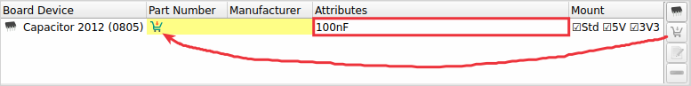
Unfortunately this procedure is a bit cumbersome, we’ll try to improve it in upcoming releases. |
|
Note that these attributes are not automatically included in the BOM.
Usually, only the For example if you want to have the attributes |
Example: Do Not Mount
A typical use-case of assembly variants is to simply exclude some components from particular assembly variants. This is done by unchecking the corresponding variants in the last column:
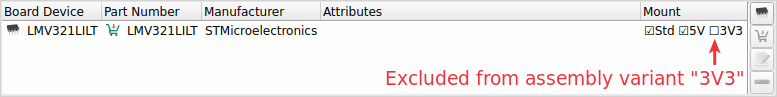
So this component won’t be contained in the BOM for 3V3, but it will be contained in the BOM for the other two assembly variants.
|
If your project contains only one assembly variant, the last column won’t display its name. In that case there will be just a plain checkbox, but this procedure works exactly the same way. |
Example: Alternative Parts (2nd Source)
Another possible use-case is to specify alternative part numbers (or attributes) for a component, to make the assembly house know which other parts they can choose if the primary part is out of stock.
This is done by selecting the corresponding assembly option row and clicking on the Add Part By MPN button multiple times, once for each alternative part. The first one is automatically considered as the primary part, while any further parts are alternative parts. The result should look like that:
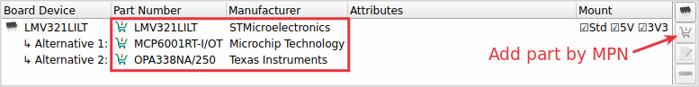
This will cause the BOM to include three additional columns (those ending
with [#] where # is an incrementing number) for each alternative
part (common columns omitted and text abbreviated for readability):
| Value | MPN | Manufacturer | Value[2] | MPN[2] | Manufacturer[2] | Value[3] | MPN[3] | Manufacturer[3] |
|---|---|---|---|---|---|---|---|---|
LMV321 |
ST |
MCP6001 |
Microchip |
OPA338 |
TI |
Instead of specifying alternative parts by MPN, you could also specify alternative parts by attributes exactly the same way — just specify attributes instead of MPNs 😉
Example: Different Assembly Variants
Last but not least, it is also possible to include a component in multiple assembly variants, but using different parts. This can be done by adding multiple rows with the Add Device button and selecting the checkboxes accordingly.
For example to assemble the part LMV321LILT in the 3V3 assembly variant, but OPA338NA/250 in the other two assembly variants, it would look like that:
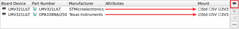
Once again, exactly the same procedure works for specifying different attributes instead of MPNs:
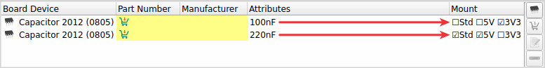
In this example, the BOM for the 3V3 assembly variant specifies 100nF for the capacitor, while the BOMs for the other variants specify 220nF.
Usage Of Assembly Data
As explained earlier, the assembly data is mainly used for the BOM export. However, there are also some other things depending on assembly data.
Schematics
In schematics, typically you see the attributes and/or MPNs next to each
component (usually in the {{VALUE}} label). But as you should now
understand, this data could depend on the assembly variant or there could
also be multiple MPNs added to a component. So the question arises, which
of them is displayed in schematics?
The rules for substituting the placeholder {{VALUE}} in schematics are
as follows:
-
If there exists at least one board, and the first board (which is considered as the primary board) contains a device for the component in question, and there is at least one part assigned to that device, any attributes from that first part are displayed in schematics.
-
If there is no such board, device or part, but the component has at least one part assigned, any attributes from that first part are displayed instead.
-
If there is no part assigned to the component at all, only the direct component attributes are taken into account (which are not depending on the assembly variant, and usually don’t contain an MPN). Note that component attributes are always taken into account anyway in case a part doesn’t specify a particular attribute (fallback mechanism).
3D Board Viewer
The 3D board viewer displays only devices which are contained in the first defined assembly variant (i.e. the default variant). So if a device is excluded from that assembly variant, its 3D model won’t show up in the 3D view.
BOM Output Job
The biggest effect of assembly data is for sure the BOM export. As explained above, for each assembly variant a separate BOM file will be created. Strictly speaking, this is not always true since it is configurable — but at least it’s the default behavior.
Let’s take a look at the options of the BOM output job:
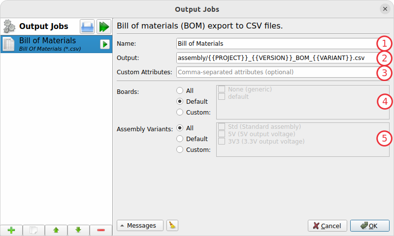
- 1) Name
-
Name of the output job as shown in the list on the left (no impact on the exported files).
- 2) Output
-
File path of the BOM files to generate. Since multiple files might be generated, placeholders are required to avoid conflicting file paths. The most important placeholder here is
{{VARIANT}}which will be substituted by the name of the assembly variant (e.g. Std). - 3) Custom Attributes
-
Comma-separated list of additional columns to be included in the BOM CSV files. For example the value
SUPPLIER,DATASHEETadds two more columns to the CSV with the component attributesSUPPLIERandDATASHEET. Usually this field can just be left empty. - 4) Boards
-
Selection of boards to export BOMs for. If your project contains multiple boards and you want to get a BOM for each of them (since they usually differ!), you may choose All or Custom here.
Attention: If multiple boards are selected, you have to add the placeholder{{BOARD}}(or any other board-specific attribute) to the output file path to avoid generating conflicting files! - 5) Assembly Variants
-
This option does exactly the same as the Boards option, just for assembly variants. Here you’ll see that All is selected by default to get a separate BOM file for each assembly variant. And that’s why the
{{VARIANT}}placeholder is contained in the output file path by default.
For the latter two options, the value Default just means that the first object is used, i.e. the first board or the first assembly variant.
|
Note that every generated BOM will contain only those components which are contained in the corresponding assembly variant. Components excluded from a particular assembly variant won’t appear in the BOM at all (no "do-not-mount" mark or something like that). Similarly, only components actually added to the selected board will be contained in the BOM. Even if a component is contained in an assembly variant, but not added to the board selected for the export, it won’t be contained in the BOM. If a component specifies multiple parts (e.g. for second source reasons), the BOM will contain additional columns to include all those parts. So the number of columns depends on the maximum number of parts added to components. Of course only those parts valid for the selected board will be contained in the BOM. |
