Component
The next element you need to create is the component for a single OpAmp. Because it is still very generic (beside the LMV321LILT there are many other OpAmps with exactly the same functionality), you should enter a generic name like Single OpAmp.
Choose New Component, enter the name, assign the component category we created previously, and specify its prefix and default value (see explanations below):
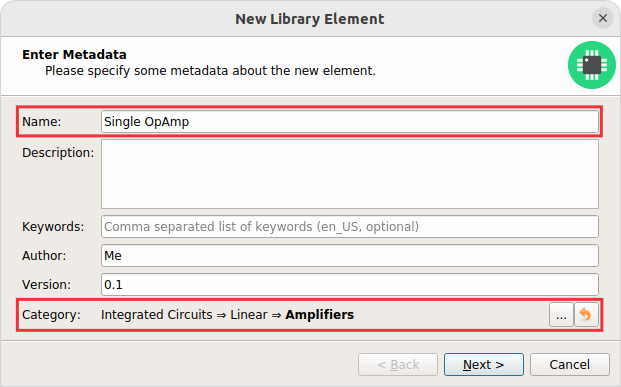
Of course you may also set more properties, but it’s not strictly required. The most important properties beside name and categories are:
- Schematic-Only
-
Check this if the component must not appear on a board, but only in the schematics. This is typically used for schematic frames.
- Prefix
-
When adding the component to a schematic, its name (designator) is automatically set to this value, followed by an incrementing number. So if you choose the prefix R, components added to a schematic will have the names R1, R2, R3 and so on. The prefix should be very short and uppercase.
- Default Value
-
In addition to the name, components also have a value assigned to it, which is typically also displayed in the schematic. For example a capacitor has its capacitance (e.g. 100nF) set as its value. When adding a component to a schematic, its value is initially set to the value specified here. The value can also be a placeholder, for example
{{MPN}},{{DEVICE}}or{{CAPACITANCE}}. If you are unsure, just leave it empty, the component editor will help you to assign a value later.
After specifying the properties, click on Next.
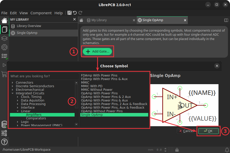
Add Gates
Now you need to choose the symbols which represent the component in schematics, called gates in this context. Most components have only one gate, but you can also add more than one. For example a Quad OpAmp could consist of a power gate and four amplifier gates. In our case, select the Single OpAmp symbol we created previously:
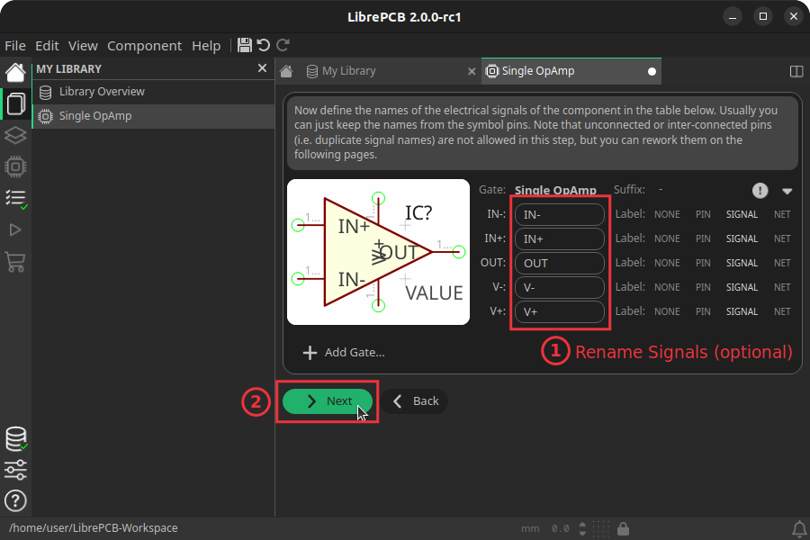
After you added all the required gates (usually only one), it is possible to rename the pins, which are called signals in this context. Renaming is required for example to ensure unique signal names if you add multiple identical gates, or to simply choose more expressive names if the symbol pin names are not suitable for a particular component. Often you can just keep the symbol pin names as-is:
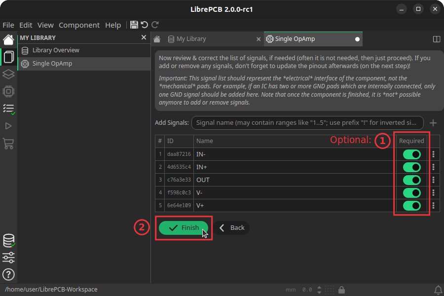
Define Signals
The next step is to define all so-called signals of a component. Signals represent the "electrical interface" of a component. For example a transistor consists of the signals Base, Collector and Emitter. For a component it’s irrelevant whether the "real" transistor has multiple emitter pads, or an additional thermal pad and so on — the component only specifies the three electrical signals.
LibrePCB automatically extracts the signals from the gates you added in the previous step, so usually you don’t have to do this by hand. But sometimes you still need to make some adjustments, like deleting unused signals or changing the properties of some signals. For our OpAmp, we check the Required checkbox of all signals to ensure the ERC will raise a warning if these signals are not connected to a net in the schematics:
Review Pin-Signal-Map
After clicking on Finish, the component is complete. It is highly recommended to review the mapping from symbol pins to their component signals, especially for more complicated cases like multi-gate components of if you made any manual changes to the component signals in the previous step. If there is any mistake, you can just correct the pin-signal-map with the dropdowns:
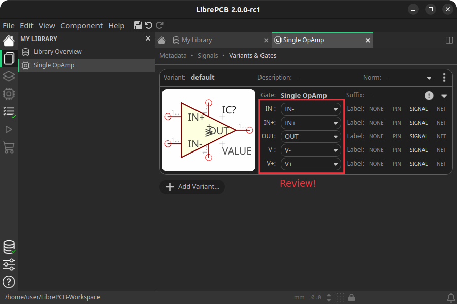
In this component editor you can also make more changes, like hiding specific symbol pin labels or specifying suffixes for gates, but that is not important for now.
|
For our simple example this procedure might feel a bit complicated. This is due to the broad flexibility of the LibrePCB library approach which will save time in the long term due to high reusability of library elements. The component which we created uses only very basic library features, but as soon as you understand the library concept in more detail, you will be able to easily create much more complicated library elements. We’re sure you will learn to love the flexibility of the library concept step by step. |
Recommendations
Following are the most important rules to create reusable components:
-
Create generic components whenever possible. Only create specific components for manufacturer-specific parts (like microcontrollers).
-
Generally name signals according their electrical purpose (e.g. Source, Drain, Gate).
-
Don’t add multiple signals which are considered as connected. Even for a microcontroller which has multiple GND pins, the component should have only one GND signal. Keep in mind that a component represents the electrical interface of a part, not the mechanical!