Create Schematics
Before starting with the board layout, a schematic will be needed. At the moment, it is not possible to create boards without creating a schematic first (we may change that in future, though we recommend anyway to always create a schematic first). So let’s see how to draw a schematic.
Add Drawing Frame
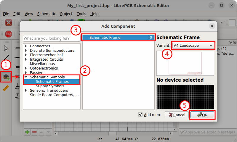
First, you may want to add a drawing frame to the schematic. Click on the Add Drawing Frame button which is already suggested, or alternatively use the Add Component button from the toolbar. Then choose the desired paper format and click OK to add the frame to the schematic:
Note that we now collapsed the left side panel to have more space for the drawing area.
Add Components/Devices
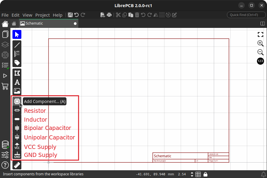
Now add all the resistors, capacitors, ICs etc. with the corresponding tool buttons to your schematic:
However, for real parts (in contrast to the schematic frame), the Add Component dialog lets you select a concrete device. Here an explanation about the displayed information:
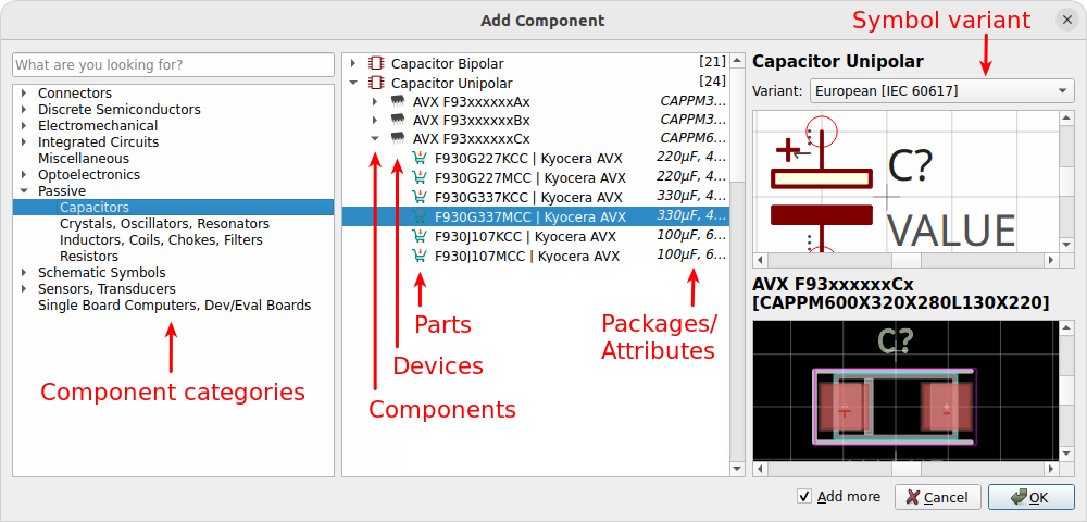
You can choose between adding a component a device or a part:
-
Component: Defines the schematic symbol and netlist signals. It’s all you need in a schematic, but it does not represent a concrete part and does not specify the package to be placed on the board.
-
Device: Defines the package to be used in the board. Basically it’s the combination of a component and a package with a particular pinout.
-
Part: Represents a real, orderable part. In addition to defining the package, it also defines the exact MPN[1] which will appear in the BOM[2].
To add something to a board, you need to choose a device or a part. However, it’s your choice whether to select it now or later when starting with the board layout. This allows to draw the complete schematics even if various packages and devices do not exist yet in your libraries.
After clicking on OK, the selected component is attached to the cursor. Click on a point in your schematics to place the component. Press Esc to finish the placement. The Add Component dialog pops up again to choose the next component. Press Esc again to leave the tool.
|
While placing components, press R to rotate or M to mirror. With Tab the focus is moved into the toolbar to allow specifying a value. |
Supply symbols like VCC or GND are added exactly the same way since these are ordinary library elements as well. However, they are also provided in a dedicated toolbar for a quick access to the most commonly used elements.
|
The Add Component dialog lists all the components, devices and parts available in the libraries you have installed in your workspace. If you are missing something, you either need to install more libraries or create your own library elements. To create your own library elements, follow the linked tutorial. You can keep the project open while working in the library editor. Afterwards, wait for the background library scan to complete (indicated as a progress bar at the bottom right of the window). Then the new library elements will appear in the Add Component dialog and are ready to be used. |
Draw Wires
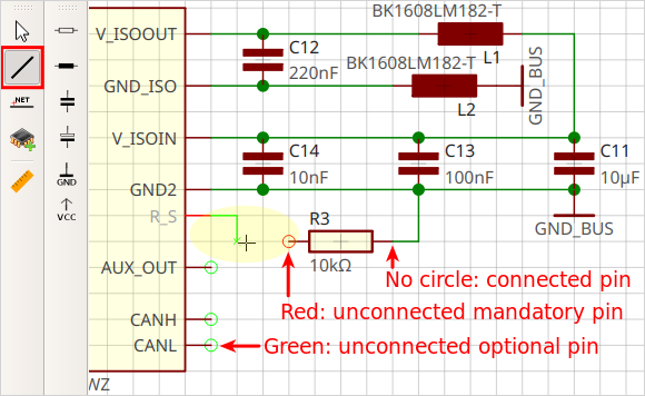
Once your schematic contains some components, the pins can be connected with the Draw Wire tool. In this tool, just click on a pin to start a new wire:
|
Pay attention to the circles around the pins. If a wire appears to be starting at a pin, but the circle is visible, it is not connected. The color of the pin circles even provide some more context:
|
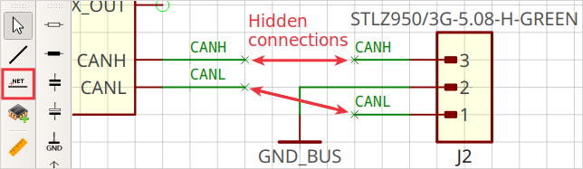
Add Net Labels
To keep schematics clean and readable, net labels may be added. They allow to explicitly specify net names, and to create hidden connections between wires of the same net name.
-
Start the tool Add Label to Net or Bus.
-
click on the wire where to attach the label.
-
Click to specify the label position.
|
While placing labels, press R to rotate. |
|
All wires in the whole project which have the same name assigned will automatically be connected, even accross schematic pages. |
Add More Sheets
For larger projects, you may want to split the schematics into multiple sheets for better readability. Just add more sheets with , then add a frame and devices the same way. Use supply symbols and net labels to connect nets across pages.
Electrical Rule Check
At latest when you’re finished with the schematics, you should check if there are no critical ERC messages. The ERC does not need to be triggered since it is automatically updated.
Open the ERC panel with the corresponding sidebar button while a schematic is opened:
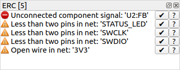
Click on a message to get more information about it and to see its location (if available) in the schematics. If you’re sure a message is not relevant, you could approve it with the eye symbol next to them, but usually warnings/errors should be fixed instead of approved.