
@ubruhin
June 12, 2026
Today we released LibrePCB 2.1.1, which includes some improvements related to FreeRouting compatibility and keyboard shortcuts on macOS, and also various small bugfixes. Check out the changelog below.
Credits
External code contributors of this release: @SiboVG
Download
The release can be downloaded for all major operating systems from our download page.
If you like LibrePCB, please consider making a small
donation to support the
ongoing development.
Thank you!
@ubruhin
May 19, 2026
Today we released LibrePCB 2.1.0, bringing cross-probing, UI themes, 3D shading, a new project library manager, automatic library updates, and many more improvements! Check out the highlights and the full changelog below.
Highlights
Cross-Probing & Net Highlighting (#1748, #1790)
LibrePCB now supports automatic, bidirectional cross-probing between schematics and boards. Whenever you select components, nets, pins or pads in one editor, the corresponding objects are highlighted in the other one, while unrelated objects are dimmed out. In addition, it is now possible to search for nets in schematics and boards — using the same dimming for unrelated objects — making it even easier to inspect and navigate complex designs!
Themes & Color Schemes (#1731, #1760)
As LibrePCB 2.0 was the first release with our new UI framework Slint, we had to focus on implementing all the basic functionality and thus keeping the UI simple. Therefore we made the decision to initially provide only a dark theme (which was not even a very nice one). Now we finally invested more time into the UI theming, resulting in an improved dark theme and a new light theme. The theme is automatically chosen according to your system theme, but of course you can manually override it in the workspace settings.
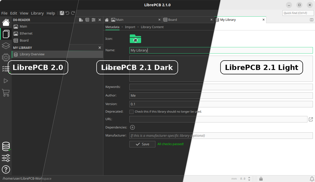
The colors of 2D canvases (i.e. schematics, boards etc.) remain independent of the UI theme to allow configuring them individually. However, the configuration of those colors has been reworked as well and now comes with several built-in color schemes. For example the dark theme experience can now be improved by simply choosing a dark schematic color scheme. In addition, it is now much easier to create custom color schemes since any color modifications are instantly applied to the opened editors.
2D Board Flip & 3D Shading (#1709, #1764)
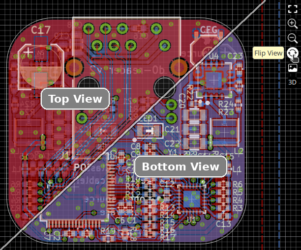
The board editor now allows flipping the 2D canvas upside-down to view the board from the bottom instead of "looking through" the board from the top. This simplifies routing the bottom board side and avoids accidentally grabbing objects on the top layer since not only the rendering is inverted, but also the "hit test" on a click — when viewing the board from the bottom, objects on the bottom layer are stacked above objects on the top layer.
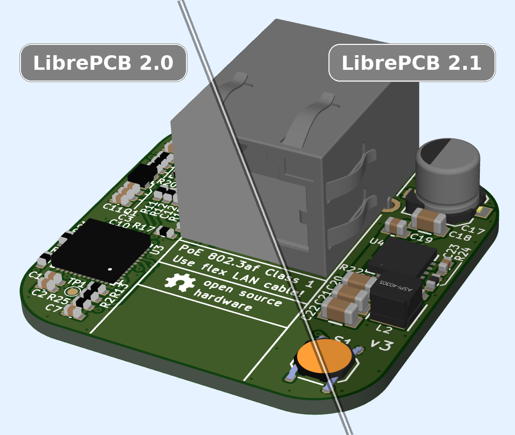
Another enhancement regarding visualization is the 3D viewer, which now applies shading to the surface of the PCB and the 3D models. A small change, but still very useful since it finally makes edges and holes of 3D models visible and generally leads to a much more realistic rendering.
Project Library Manager (#1788)
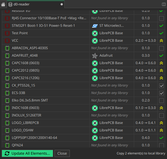
This release introduces a new Project Library Manager to give you a clearer overview of the library elements bundled in a project. It lists all bundled elements, shows which workspace library they come from, and compares their bundled and latest versions.
If library elements are not found in any workspace library, you can now save them from the project directly into a workspace library. This is especially useful for projects you received from someone else or migrated from EAGLE.
The old Project Library Updater is still used to update the project library elements, but the goal is to also integrate this functionality into the new library manager in a future release.
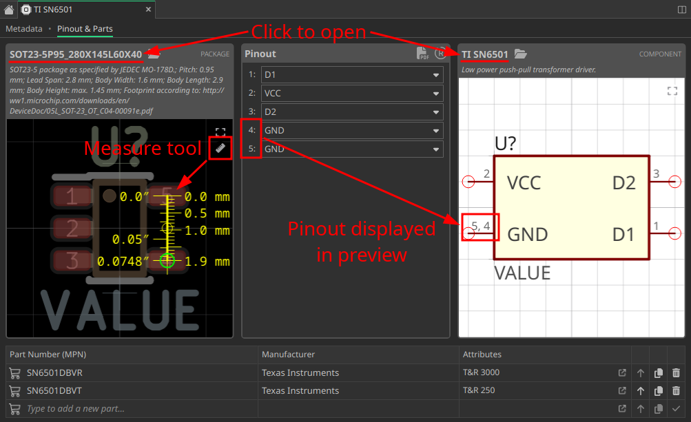
Device Editor Improvements (#1780, #1768, #1769, #1772)
The device editor gained some new features to increase productivity:
-
The dependent package and component can be clicked to open them in a new tab
-
The pinout is now visualized in the component preview, simplifying its review
-
The previews can be zoomed & panned to inspect them in detail
-
A measure tool allows you to verify whether the selected package really has the desired dimensions
Add Planes at Lightning Speed (#1745)
Another small but useful productivity improvement has been implemented for the board editor. Adding copper planes is a very common task, while usually they span just the whole board, thus it seems unnecessary to draw their outline manually. For this typical case, planes can therefore now be added with a single click — which also automatically selects the next lower layer, so you can just continue clicking for each layer. After reaching the bottom layer, the tool exits automatically.
Automatic Library Updates (#1776)
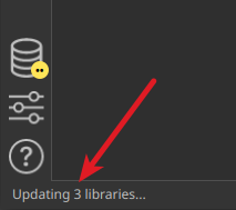
So far, the libraries installed through the library manager had to be kept up to date by installing the updates manually. However, this was unnecessarily cumbersome — since those libraries are installed read-only, there is no harm in letting LibrePCB update those libraries automatically, so LibrePCB 2.1 will do this now for you. It checks for updates once per day (like LibrePCB 2.0 already did), and installs the updates automatically if there are any.
Note that in some special cases — when the update requires uninstalling any libraries or installing additional libraries — a manual confirmation will still be required to avoid any surprises.
|
This feature can be configured in the workspace settings. You can choose any of Disable Completely, Check Only (LibrePCB 2.0 behavior), Check & Notify (Popup), and Check & Install. |
Changelog
Schematic & Board Editor:
-
Implement automatic cross-probing between schematic & board (#1748)
-
Implement project library manager (#1788)
-
Support searching for nets in schematics & boards (#1790)
-
Support flipping 2D board view to bottom side (#1709)
-
Show properties of selected components, devices, pads etc. (#1743)
-
Support drawing arcs in board polygon/zone tools (#1770)
-
Support auto-adding planes to boards (#1745)
-
Support placing remaining component gates (#1791)
-
Indicate forced net name mismatches in schematics (#1754)
-
Add DRC check for board outline intersections (#1811)
-
Support 'F' shortcut to flip layer while drawing trace (#1808)
-
Hide unnecessary information in component properties dialog (#1753)
-
Draw symbol crosses only when selected (#1736)
-
Fix missing "save?" message box in project library updater (#1724)
-
Fix outdated ERC messages count in sidebar (#1734)
-
Fix missing Ctrl+Shift+L shortcut in schematic editor (72650b08)
Library Editor:
-
Require explicit unlock to make breaking changes in library elements (#1777)
-
Device editor: Support measure tool in package preview (#1780)
-
Device editor: Visualize pinout in the component/package previews (#1769)
-
Device editor: Support opening dependent component & package (#1772)
-
Device editor: Support zoom & pan in component/package previews (#1768)
-
Symbol/package editors: Snap cursor to existing vertices (#1752)
-
Package editor: Explicitly make newly added 3D models visible (#1730)
-
Category check: Warn about invalid parent category (#1738)
-
Fix unreliable keyboard shortcuts in library editor tabs (#1766)
-
Fix approvals not updated after symbol/package reload (#1706)
-
Fix crash in library tab due to categories with endless recursion (#1737)
User Interface:
-
Rework/improve dark theme & add light theme (#1731)
-
Add dark color schemes for schematic editor & 3D views (#1760)
-
Implement shading in 3D views (#1764)
-
Support moving tabs to other windows through context menu (#1746)
-
When closing/moving tabs, switch back to previous tab (#1747)
-
When closing a library tab, ask for saving modifications (#1774)
-
Automatically close library when closing its last tab (#1775)
-
Memorize & restore side panel page on tab switch (#1810)
-
Support resizing side panel (#1783)
-
Accept user input "mil" as unit "mils" (#1716)
-
Keep auto-fit in 2D views active until manual zoom/pan (#1773)
-
Limit zoom in 2D canvas to a reasonable range (#1704)
-
Support rotating 3D views with keyboard shortcuts (51020bb0)
-
Swap buttons for new symbol / new package in library tab (1bdd2443)
-
Do not auto-correct invalid pad/via drill/size properties (#1717)
-
Fix schematic/board tab titles not matching documents panel items (60067cc1)
-
Fix unintentionally focusing search field (f8e3d319)
-
Fix focus issue after closing a modal dialog (#1800)
Miscellaneous:
-
Automatically update remote libraries (4 configurable modes) (#1776)
-
Support loading semi-transparent STEP models (#1755)
-
Support changing opacity of 2D background image (#1708)
-
Trim whitespace around empty attribute substitutions (#1807)
-
Make default grid style configuration independent of themes (#1757)
-
Split themes configuration into 3 separate color schemes (#1758)
-
Apply color scheme modifications immediately (live preview) (#1749)
-
Support switching application language at runtime (#1721)
-
Do not change locale settings when switching language (#1723)
-
List system locale in "About LibrePCB" details (#1733)
-
FreeBSD: Use
sysctl()to determine process name for file locks (#1806) -
Add workaround for problems with libfreetype 2.14 (#1799)
-
Fix custom keyboard shortcuts not working (95758687)
-
Fix offset when pasting objects from other tabs (#1735)
Building/Packaging/Deployment:
-
Update
parseagleto get rid ofQtXMLdependency (#1763) -
Linux: Support disabling desktop integration by environment variable (8a92ff80)
-
AppImage: Update releases to Qt 6.11.1 (#1792)
-
AppImage: Fix system theme detection & native file dialogs (#1778)
-
MacOS: Update x86_64 releases to Qt 6.5.8 (#1787)
-
MacOS: Set up code signing for x86_64 releases (OSSign/#6)
-
OpenBSD: Fix linking error of
librepcbandlibrepcb-cli(#1702) -
Fix build error with OCCT 8.0.0 (#1804)
-
Fix outdated requirements & installation instructions (830054f4)
Internal:
-
Implement low-level math functions in Rust with
libm(#1739) -
Implement
Length,Angle,Point,VertexandVertexVecin Rust (ff168c01, e9d1a5e2) -
Add Rust unit tests to reach 100% coverage & enforce it on CI (#1771)
-
Set up and enforce static C++ code analysis with
clang-tidyon CI (#1785) -
Enforce strict coding style & spell check on CI (#1719, #1784)
-
Support using rust-core without FFI in external projects (#1713)
-
Refactor schematic text rendering without using
QStaticText(#1765) -
Migrate all remaining CI jobs from Azure Pipelines to GitHub Actions (#1786)
Credits
A big thank you to our sponsors and to the community helping us with translations, pull requests, donations and other contributions! 🎉
External code contributors of this release: @Girish4489, @stoeckmann, @benoit-canet, @melak
Download
The release can be downloaded for all major operating systems from our download page.
If you like LibrePCB, please consider making a small
donation to support the
ongoing development.
Thank you!
@ubruhin
February 22, 2026
Today we released LibrePCB 2.0.1, which brings a few small improvements (e.g. better HiDPI screen support) and various bugfixes. See the full changelog below.
Changelog
Library Editor:
-
Fix error when creating new library with long name (#1685)
Miscellaneous:
-
Auto-open board when opening a project (#1683)
-
Display properties of selected schematic- & board objects (#1698)
-
Show grid interval keyboard shortcut in tooltip (c88603f4)
-
Slightly improve color contrast of Qt checkboxes (7abcbc28)
-
Fix dropdowns opening outside of screen (#1694)
-
Fix blurry icons & graphics for HiDPI scale factor > 100% (#1691)
-
Fix keyboard modifiers not working in graphics views (#1692)
-
Fix sensitive detection of touchpad scroll direction (#1695)
-
Fix flaky global cursor position transform in editors (#1689)
-
Fix mouse cursor flickering (6dff7cfa)
-
MacOS: Fix loosing focus after adding component to schematic (#1687)
Credits
External code contributors of this release: @megabyte6
Download
The release can be downloaded for all major operating systems from our download page.
If you like LibrePCB, please consider making a small
donation to support the
ongoing development.
Thank you!
@ubruhin
January 28, 2026
I am very proud to announce the release of LibrePCB 2.0.0 today, after 10 months of hard work! The implementation of a completely new UI with modern technologies marks the beginning of a new era in the history of LibrePCB. But there are also many other improvements and new features, check out the details below.
@ubruhin
January 13, 2026
I’m very excited to announce that LibrePCB 2.0 is feature-complete and that a first release candidate is available for download!
@ubruhin
December 25, 2025
@ubruhin
September 12, 2025
@ubruhin
August 5, 2025
The past 3 years were very exciting for me and the LibrePCB project, completely different to the previous 10 years of the project’s existence. With this blog post I’d like to give you some insights about my "new" everyday life.
May 20, 2025
March 24, 2025
December 1, 2024
October 17, 2024
August 23, 2024
August 8, 2024
April 3, 2024
December 30, 2023
September 24, 2023
August 21, 2023
May 15, 2023
April 13, 2023
October 3, 2022
September 8, 2022
January 28, 2022
November 2, 2021
October 4, 2020
May 3, 2020
January 3, 2020
November 30, 2019
July 14, 2019
April 21, 2019
March 20, 2019
December 3, 2018
November 25, 2018
November 4, 2018
October 21, 2018
September 15, 2018
April 21, 2018
January 2, 2018
October 30, 2017
September 13, 2017